Slabulous
Exciting times to be alive and kickin!
So much is happening around here at Atamai Village. With the trees bursting with juicy organically grown fruits and the produce box delivery system finding its way into reality, we are getting a steady stream of our food directly from the land around us. This is very gratifying and enables us the tangible benefits of having the bulk of our weekly produce grown locally. We still strive to attain greater levels of self sufficiency as we progress our eco life.
Many villagers have been busy bottling and preserving ripe fruits, which will hopefully enable the summer season to stretch further. We have found it enriching to eat with the seasons, even if at times we have more Basil than we know what to do with - but that's what pesto is for :)
We have also had a steady flow of visitors; both friends from Christchurch as well as visitors to Atamai. Most of the times we welcome them, but other times we just tell them to go jump in the lake! This is exactly what James and Penny (and family) decided to do. Pay no notice to that guy on the right, I think he's a bit stoned!

Solar Panels go up
A few weeks were spent installing the rack system for the solar panels on the pole shed. These racks are capable of being adjusted on tilt angle so that they can be positioned to the perfect angle permanently or with the seasons. However the weight of the mounted panels are a daunting, I'll have to come up with some kind of mechanism to change the angle or use volunteer power.


The raising of the solar panels was an interesting exercise. I put the word out and most of the village turned out to help. It was great having everybody there, many hands sure make light work.


Now I just have to wait for all my inverter componentry before things can proceed further. I have got most of the components now, I'll talk more about this system in a different post.
You must be curious enough about the title of this blog (or just perplexed) to have read this far. The "Slab" or housing foundation is my next chapter, one that has kept me busy for weeks, if not months!
House Build:
Firstly, we finally got our consent to build our house, waaa hooo!!!
So things have started to get busy around here. The first part of the process is of course to build ourselves a slab that will be the foundation for our house - little did I realise how complex an endeavour this really is!
Step 1: You dig?
If you don't, that's ok - I found John to be quite an excellent digger driver. He cleared the top soil from our platform revealing the underlying separation point granite sand substrate. Following this he spread out some clean granite sand to the perimeter of the building platform, nice and level. This was about a 2 day job.


Step 2: Piles
Now we need to get some piles in the ground. We are located halfway up a 60m hill, and our platform was created with some cut into the hill and some compacted fill from the cut. Since our house will be straddling the cut/fill line, we need a decent amount of hold on the original ground in order to be stable, particularly in the event of an earthquake. This means that our house (which is double storey) will need a swag of piles varying in lengths from 2.7m down to 1.2m, a dazzling 54 of them!
In this case we had chosen to use H5 treated radiata pine round 175 SED (small end diameter) poles over using concrete piles. This was carefully considered because of these reasons:
- they were cheaper
- they have less embodied carbon and energy, at the best they would be carbon negative because the tree sequestered CO2 out of the air during its life.
- in a low oxygen and moisture environment, they should last a long time. The H5 treatment of the wood would ensure a reasonable drying time in the ground. I didn't like the idea of using treated timber, but options for hardwood were limited due to regulations and costs.
- the wood acts to secure the slab without causing a thermal bridge to the ground, as a concrete pile would.
Some piles were ordered and piled for testing the ground and how compacted it was.


Once the test piles were driven and lengths verified, the rest of piles were ordered. The profiles for the floor were raised to get the finished floor height, and also so that the rest of the piles could be marked for piling.
To make things easier, the pile locations are drilled out with an auger before driving the piles in. In this case we used a machine mounted auger. It was pretty hard work however and took a lot of effort to drill all the pile holes required. What we should have done is to get a cantilevered version which would have made the job far easier - next house eh! ;)

Step 3: Installing the drains
 The next stage was call a local friendly plumber and get the drains sorted. You can see above the laying of the drains for the bathroom area of the house. This was repeated for the en suite, laundry, toilet and kitchen areas.
We have planned a larder room in our house. This room is designed to be insulated from the rest of the house and be permanently cooled as close to ground temperatures as possible. This gives an effective zero energy cool dry store for storing some of our perishables fresher for longer. We also plan to have a cool wet larder outside of the house, but that is for later.
For our internal larder we installed an underground pipe that rises into the larder room. This together with the solar chimney convective effect of the house is meant to draw cool air from the ground into the larder room to keep it at a consistent and cool temperature - perfect for storing some types of perishable food. The pipe is buried relatively deep about 1.5m below the ground level. This was done because a series of other service pipes and cables will have to traverse laterally above this pipe at a later stage.


While the drains were being done, I took the liberty to also install the conduit pipe where the electrical and communications cable will be directed. In this mix will include a 2 phase cable (for redundancy and extra solar generation capacity), a 48V DC cable (battery direct), a CAT6 Ethernet cable and potentially also a blow duct conduit for blowing fibre optic cabling through at a later date. This is the main reason why I choose to use a chunky 100mm diameter pipe - hoping it will all fit :)
The existing solar panels which are mounted on our shed will generate 3kw of power peak (including inverter losses), but additional solar panels may be mounted on the main house as well. I anticipate using grid tie solar inverters either for direct injection into the grid, or injection into the micro grid. I'll reserve this technical detailing for another blog post - it is very interesting stuff!

Step 4: Slab base preparation
Our slab is based on a rib-raft slab design, if you turn it upside down it will look like a waffle. The criss crossing of ribs reinforced with steel gives the floor incredible stiffness and strength without the use of a lot of concrete. It's no surprise that this technology of flooring was first used to suspend mid floor levels in multi storey buildings. In our case, the rigidity adds to the house's ability to width stand better an earthquake event.
The ribs are created with pods of polystyrene 200mm thick, cut to order to the correct dimensions, and spaced apart using plastic or metal spacers. Our house design allows for Adobe brick veneer on some internal walls which means additional steel caging is required in the footing to support the extra weight of the bricks. The weight is in the region of tonnes per wall, so this certainly needs to be engineered to suit. The main purpose of the Adobe brick veneer is both for beauty as well as adding to thermal mass to regulate the temperatures in the house. It has the extra benefit of keeping the air moisture levels in the house at comfortable levels (a trait of Adobe). The engineer we choose, Richard Walker, is none other than the guy who wrote (or was instrumental in) the mud brick building code in New Zealand, a long long time ago.
Although the 200mm polystyrene pods act as a good thermal insulator, the ribs are effective thermal sinks. In our 130m2 footprint, we have about 30m2 of thermal bridging from the ribs - this amounts to a loss in effective R-value of the floor, and inefficient loss from our heated slab to the ground which remains at a relatively constant temperature. To resolve this, we decided to insulate under all of the ribs using high density foam. This proved to be a challenging exercise as you will see in the pictures that follow.
Firstly the AP20 (20mm) gravel hard fill is spread across the entire site to bring the level of ground up. It had to also be extended 1m out from the perimeter to support the foundation boxing.

Subsequent to this, the rib channels we raked down to a suitable height and the high density foam placed. You can see below that each of the foam pieces also have some DPM (damp proof membrane) attached to them - this was theoretically to maintain the R value of the foam in a moist earthy environment.
The cutting of the foam and fitting of the DPM was a fiddly process, as was the raking and laying. I wondered if the DPM is really required seeing the foam was rather dense and would have been relatively immune to water ingress. Further complications were had because the seasonal rains had arrived - this was not only uncomfortable to work in, it also pooled water in the DPM encasement which effectively "contained" the rain water! This meant that the foam became buoyant relative to the DPM, which started lifting it up from the raked areas. It was a frustrating time to say the least!
If I were to ever attempt this again, I would obtained 250mm thick pods and use the high density foam as spacers in the rib wells. The whole thing would have sat on the hard fill and DPM uniformly placed everywhere before the pods and rib insulation was fitted, making the whole process less time consuming and cheaper. I had considered doing this before hand, but there was one additional complication. The boxing around the perimeter is only 300mm high, and this 250mm pod + the 100mm floor would have mean a 50mm extension was required. This wasn't a straight forward exercise and would have led to a substantial cost increase for customized boxing. What we could have done however was to raise the AP20 levels around the 1m perimeter by 50mm and voila, it would have saved many back breaking hours!!
You live, you learn ...


Step 5: Boxing, PODs and Steel
I called on the experience of Barnett Construction to do the boxing and install of the slab. They have a specialised boxing system that is modular, versatile, rigid and strong - they managed to install all of the boxing in about 4 hours, that's an impressive feat.


The 300mm laminated lacquered plywood then gets attached to the supports. All the boxing lengths were predetermined before coming to site, and everything just fitted in like clock work. These guys are boxing professionals! ;)


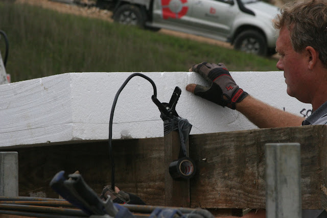
The next stage involves placing a large DPM spread over the entire floor, and placing the pods with spaces down over the DPM. Steel is added in the lower part of the ribs.

The DPM is cut tightly around each pile, allowing a snug fit over it which will allow the concrete to key around the pile properly, whilst still working as a reasonably effective DPM layer. Note, tape doesn't really like sticking to the wooden pile.

Some of the areas requiring additional wire caging for Adobe wall support is placed in the appropriate rib channels.


Not too far into the process we came unto a stumbling block. The company supplying the pods did not cut out an appropriate rebate/recess in the pods that were meant for the shower areas. The rebate is there so that the shower levels can be set (using leveling compound) after the concrete has been poured and the walls are up. Predominantly this was meant to be for a tiled floor, but we are still considering alternative options for our showers - ideas are welcome.
As the pod company wasn't able to deliver replacement pods until the next day, we jigged together a hot wire cutter. A bit of thin gauge tie wire (used in the automatic tie wire guns) was stretched across a piece of wood, and my car jump starter bolted to each end to power it. This seemed like a recipe for entertainment, but it actually worked quite well. The wire heated up and the cutting began - however the wire would break quite easily under tension. After a few goes, we tried using wire from my MIG welder instead, this proved to be a much better solution.
I knew I'd find that MIG welder handy one day ;)


The boys left that day very chuffed - they had finished the day's job, a great effort all around.
Step 6: Fitting the hydronic underfloor heating coils
The next day Alan from Sola Nelson would come to install the underfloor hydronic (water) pipes which we would use for heating the slab.


Step 8: Concrete cutting
Now that the concrete has had a couple of days to set, the concrete cutter comes to cut a control expansion joint in the slab to help reduce chance of cracking. Our engineer has advised that the expansion cut should be done at a place where there is the highest likely hood of cracking which is 10-20mm off the rib's edge. The rib itself is pretty strong with all the reinforcing and thus the highest areas of tension is in the place immediately adjacent to the rib. Hopefully this will be good enough to help keep the slab from future cracks.


However we expect that despite all this measures, we might still get cracks - something that is entirely part of what concrete does.The expansion joint will be filled with grout later, or a piece of metal before the polishing commences.
Phew, now we are done - what a journey!! I'm sure the rest of the build will pose its own challenges, but I'm really glad that our foundation has been poured and I can breathe a sigh of relieve ...
... until next blog!
Adios amigos!
:)
So much is happening around here at Atamai Village. With the trees bursting with juicy organically grown fruits and the produce box delivery system finding its way into reality, we are getting a steady stream of our food directly from the land around us. This is very gratifying and enables us the tangible benefits of having the bulk of our weekly produce grown locally. We still strive to attain greater levels of self sufficiency as we progress our eco life.
Many villagers have been busy bottling and preserving ripe fruits, which will hopefully enable the summer season to stretch further. We have found it enriching to eat with the seasons, even if at times we have more Basil than we know what to do with - but that's what pesto is for :)
We have also had a steady flow of visitors; both friends from Christchurch as well as visitors to Atamai. Most of the times we welcome them, but other times we just tell them to go jump in the lake! This is exactly what James and Penny (and family) decided to do. Pay no notice to that guy on the right, I think he's a bit stoned!

Solar Panels go up
A few weeks were spent installing the rack system for the solar panels on the pole shed. These racks are capable of being adjusted on tilt angle so that they can be positioned to the perfect angle permanently or with the seasons. However the weight of the mounted panels are a daunting, I'll have to come up with some kind of mechanism to change the angle or use volunteer power.


The raising of the solar panels was an interesting exercise. I put the word out and most of the village turned out to help. It was great having everybody there, many hands sure make light work.


Now I just have to wait for all my inverter componentry before things can proceed further. I have got most of the components now, I'll talk more about this system in a different post.
You must be curious enough about the title of this blog (or just perplexed) to have read this far. The "Slab" or housing foundation is my next chapter, one that has kept me busy for weeks, if not months!
House Build:
Firstly, we finally got our consent to build our house, waaa hooo!!!
So things have started to get busy around here. The first part of the process is of course to build ourselves a slab that will be the foundation for our house - little did I realise how complex an endeavour this really is!
Step 1: You dig?
If you don't, that's ok - I found John to be quite an excellent digger driver. He cleared the top soil from our platform revealing the underlying separation point granite sand substrate. Following this he spread out some clean granite sand to the perimeter of the building platform, nice and level. This was about a 2 day job.


Step 2: Piles
Now we need to get some piles in the ground. We are located halfway up a 60m hill, and our platform was created with some cut into the hill and some compacted fill from the cut. Since our house will be straddling the cut/fill line, we need a decent amount of hold on the original ground in order to be stable, particularly in the event of an earthquake. This means that our house (which is double storey) will need a swag of piles varying in lengths from 2.7m down to 1.2m, a dazzling 54 of them!
In this case we had chosen to use H5 treated radiata pine round 175 SED (small end diameter) poles over using concrete piles. This was carefully considered because of these reasons:
- they were cheaper
- they have less embodied carbon and energy, at the best they would be carbon negative because the tree sequestered CO2 out of the air during its life.
- in a low oxygen and moisture environment, they should last a long time. The H5 treatment of the wood would ensure a reasonable drying time in the ground. I didn't like the idea of using treated timber, but options for hardwood were limited due to regulations and costs.
- the wood acts to secure the slab without causing a thermal bridge to the ground, as a concrete pile would.
Some piles were ordered and piled for testing the ground and how compacted it was.


 |
| The measuring tape is dangled like a pendulum to see if the pole is going in straight. |
 |
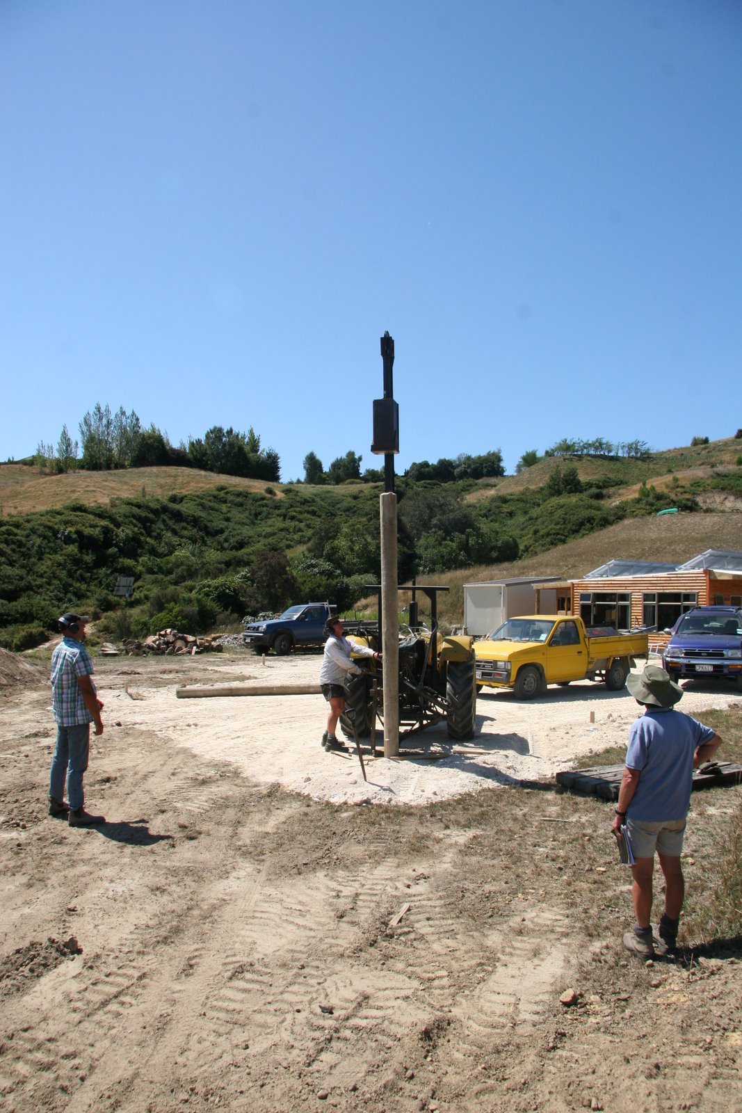
| The characteristics of the ground was evident by the driving blow required to sink it. The "hammer" consists of a 200kg weight which is dropped on the pole. Note the pole is blunt when it is placed on the ground, but it does go in with the smaller end first. If the pile doesn't move more than 100mm in 10 blows at a pre-defined drop height (based on kJoules per blow), then one can confidently say that the pile is deep enough in the ground. |


 | ||
| Richard our engineer checks the piling and records the data. |

 |
| This is a close up of the tractor mounted pile driver machine. It hooks on to the tail shaft of the tractor which has a series of belts and pulleys which act as a clutching mechanism as well as a reduction ratio. The lever which is moved by the operator pushes the belt unto the shaft which rotates the drum of high tensile steel rope. This lifts the weight up on the i-beam guide post. When the lever is pulled away, the weight free falls unto the pile. The operator times the lever so that it is reactivated just a second before the weight hits the pile, which allow the full blow to be delivered to the pile without the wire getting too slacked. |
Once the test piles were driven and lengths verified, the rest of piles were ordered. The profiles for the floor were raised to get the finished floor height, and also so that the rest of the piles could be marked for piling.
 |
| Profiles up and ready! |
To make things easier, the pile locations are drilled out with an auger before driving the piles in. In this case we used a machine mounted auger. It was pretty hard work however and took a lot of effort to drill all the pile holes required. What we should have done is to get a cantilevered version which would have made the job far easier - next house eh! ;)

 | |
| Here you can see the end result, all the piles are in and cut short. The green paint on them is extra preservative to coat the cut face of the pile. |

We have planned a larder room in our house. This room is designed to be insulated from the rest of the house and be permanently cooled as close to ground temperatures as possible. This gives an effective zero energy cool dry store for storing some of our perishables fresher for longer. We also plan to have a cool wet larder outside of the house, but that is for later.
For our internal larder we installed an underground pipe that rises into the larder room. This together with the solar chimney convective effect of the house is meant to draw cool air from the ground into the larder room to keep it at a consistent and cool temperature - perfect for storing some types of perishable food. The pipe is buried relatively deep about 1.5m below the ground level. This was done because a series of other service pipes and cables will have to traverse laterally above this pipe at a later stage.


 |
| A compactor is used to compact the fill dirt once it has been put back in the ground. This ensures it doesn't just all wash away in the next rain. This certainly has paid off as we are now in our rainy season and this fill is holding well. |
 |
| All the drains done. The blue sheeting is placed around each pipe so that a bit of wiggle room is created enabling the slab to move relative to the pipes. Some houses require a larger and more solid sleaving around the pipes, but in our case the slab will be keyed into the piles which will limit the lateral movement of the slab dramatically. |
While the drains were being done, I took the liberty to also install the conduit pipe where the electrical and communications cable will be directed. In this mix will include a 2 phase cable (for redundancy and extra solar generation capacity), a 48V DC cable (battery direct), a CAT6 Ethernet cable and potentially also a blow duct conduit for blowing fibre optic cabling through at a later date. This is the main reason why I choose to use a chunky 100mm diameter pipe - hoping it will all fit :)
The existing solar panels which are mounted on our shed will generate 3kw of power peak (including inverter losses), but additional solar panels may be mounted on the main house as well. I anticipate using grid tie solar inverters either for direct injection into the grid, or injection into the micro grid. I'll reserve this technical detailing for another blog post - it is very interesting stuff!

Step 4: Slab base preparation
Our slab is based on a rib-raft slab design, if you turn it upside down it will look like a waffle. The criss crossing of ribs reinforced with steel gives the floor incredible stiffness and strength without the use of a lot of concrete. It's no surprise that this technology of flooring was first used to suspend mid floor levels in multi storey buildings. In our case, the rigidity adds to the house's ability to width stand better an earthquake event.
The ribs are created with pods of polystyrene 200mm thick, cut to order to the correct dimensions, and spaced apart using plastic or metal spacers. Our house design allows for Adobe brick veneer on some internal walls which means additional steel caging is required in the footing to support the extra weight of the bricks. The weight is in the region of tonnes per wall, so this certainly needs to be engineered to suit. The main purpose of the Adobe brick veneer is both for beauty as well as adding to thermal mass to regulate the temperatures in the house. It has the extra benefit of keeping the air moisture levels in the house at comfortable levels (a trait of Adobe). The engineer we choose, Richard Walker, is none other than the guy who wrote (or was instrumental in) the mud brick building code in New Zealand, a long long time ago.
Although the 200mm polystyrene pods act as a good thermal insulator, the ribs are effective thermal sinks. In our 130m2 footprint, we have about 30m2 of thermal bridging from the ribs - this amounts to a loss in effective R-value of the floor, and inefficient loss from our heated slab to the ground which remains at a relatively constant temperature. To resolve this, we decided to insulate under all of the ribs using high density foam. This proved to be a challenging exercise as you will see in the pictures that follow.
Firstly the AP20 (20mm) gravel hard fill is spread across the entire site to bring the level of ground up. It had to also be extended 1m out from the perimeter to support the foundation boxing.

Subsequent to this, the rib channels we raked down to a suitable height and the high density foam placed. You can see below that each of the foam pieces also have some DPM (damp proof membrane) attached to them - this was theoretically to maintain the R value of the foam in a moist earthy environment.
The cutting of the foam and fitting of the DPM was a fiddly process, as was the raking and laying. I wondered if the DPM is really required seeing the foam was rather dense and would have been relatively immune to water ingress. Further complications were had because the seasonal rains had arrived - this was not only uncomfortable to work in, it also pooled water in the DPM encasement which effectively "contained" the rain water! This meant that the foam became buoyant relative to the DPM, which started lifting it up from the raked areas. It was a frustrating time to say the least!
If I were to ever attempt this again, I would obtained 250mm thick pods and use the high density foam as spacers in the rib wells. The whole thing would have sat on the hard fill and DPM uniformly placed everywhere before the pods and rib insulation was fitted, making the whole process less time consuming and cheaper. I had considered doing this before hand, but there was one additional complication. The boxing around the perimeter is only 300mm high, and this 250mm pod + the 100mm floor would have mean a 50mm extension was required. This wasn't a straight forward exercise and would have led to a substantial cost increase for customized boxing. What we could have done however was to raise the AP20 levels around the 1m perimeter by 50mm and voila, it would have saved many back breaking hours!!
You live, you learn ...

 |
| You can see the DPM encasing the foam, which filled up with water when the rains came. The foam was attached to the ground using some long nails, but these lifted when the foam became buoyant. |

 |
| Katie helps with the tidy up of some of the ribs that were too close to the piles. This would prevent the concrete from properly keying into the pile. A shovel might not be the most elegant tool for cutting foam, but it is efficient! |
Step 5: Boxing, PODs and Steel
I called on the experience of Barnett Construction to do the boxing and install of the slab. They have a specialised boxing system that is modular, versatile, rigid and strong - they managed to install all of the boxing in about 4 hours, that's an impressive feat.


The process they use starts with checking the string lines, then jack hammering pins into the ground. The boxing supports get screwed to the pins, shown below.


The 300mm laminated lacquered plywood then gets attached to the supports. All the boxing lengths were predetermined before coming to site, and everything just fitted in like clock work. These guys are boxing professionals! ;)


The next stage involves placing a large DPM spread over the entire floor, and placing the pods with spaces down over the DPM. Steel is added in the lower part of the ribs.
 |
| Plastic spacers are added in between the pods to space them at the correct distance apart. |
 |
| The lower steel D12 rebars are added. |

The DPM is cut tightly around each pile, allowing a snug fit over it which will allow the concrete to key around the pile properly, whilst still working as a reasonably effective DPM layer. Note, tape doesn't really like sticking to the wooden pile.

Some of the areas requiring additional wire caging for Adobe wall support is placed in the appropriate rib channels.

Richard our engineer inspects the progress on the floor as it progresses. He is happy, hence so is everyone else :)

Not too far into the process we came unto a stumbling block. The company supplying the pods did not cut out an appropriate rebate/recess in the pods that were meant for the shower areas. The rebate is there so that the shower levels can be set (using leveling compound) after the concrete has been poured and the walls are up. Predominantly this was meant to be for a tiled floor, but we are still considering alternative options for our showers - ideas are welcome.
As the pod company wasn't able to deliver replacement pods until the next day, we jigged together a hot wire cutter. A bit of thin gauge tie wire (used in the automatic tie wire guns) was stretched across a piece of wood, and my car jump starter bolted to each end to power it. This seemed like a recipe for entertainment, but it actually worked quite well. The wire heated up and the cutting began - however the wire would break quite easily under tension. After a few goes, we tried using wire from my MIG welder instead, this proved to be a much better solution.
I knew I'd find that MIG welder handy one day ;)


 |
| The shower pod rebated and ready to be placed. |
 |
| The pod place with the shower drain poking through. |
Step 6: Fitting the hydronic underfloor heating coils
The next day Alan from Sola Nelson would come to install the underfloor hydronic (water) pipes which we would use for heating the slab.

This process involved setting out the pipes over the top of the pods using special clips which attach to polystyrene. The idea is to ensure good coverage of the areas that are exposed for heating, and making sure the total lengths of pipes in each of the zones are nearly the same (within 10m of each other). This is so that the overall flow rate in each of the zones are reasonably well matched and easier to control. The tricky bit is to ensure you have enough length to get you "home" to the manifold, but sometimes having too much can be just as problematic.
Additionally a thinner 125 micron DPM sheet layer was added to the top of the polystyrene sheet. DPMs are useful for two things, preventing moisture from penetrating and also to allow a slip layer for the concrete when it wants to shrink. The slip layer helps prevents cracking, which is the reason why the DPM sheet was added to the top of the pods.


 |
| Each of the zones return to a central point where the distribution manifold will be located. |

 |
| You can see in this picture that the larder room to the south side of the house doesn't have an insulation pod installed. This is so that it would couple better to the ground. The sump to the right of the boxing is where the underground pipe surfaces into the inside of the larder. The wooden boxing is there as an insulator, so that the larder doesn't get affected by the heated concrete floor slab surrounding it. Concrete will be filled both inside and outside of the boxing. |
 |
| This is a close up of the larder pipe and the sump put in place with a little bit of cement. |
 |
| Additional D12 rods were attached to the corners where the concrete is most likely to crack. |
 |
| You can see here that each of the ribs were also tied in a criss cross fashion so that the channels were very well connected. |
 |
| You can see the wooden trays here where the shower rebates are placed. Note the extra D12 rebars on the corner again. |
 |
| No this isn't a Christmas tree :) I installed additional pipe to push down slab thermal sensors at a later time so I can monitor what the slab is doing. I placed one in each of the 6 zones and added others for good "measure" :) ... for instance I added a probe pipe to the centre bottom of the rib so I could get a good reference temperature reading of the overall ambient temperature of the slab. It will be interesting to get the data once I've installed the probes. |
Step 7: The pour

The concrete pumper truck and mixer arrives at the house at 6:30am ... yea, believe it! Yawn ... However the guys were trying to maximise the total duration of good weather which was forecast for the day. A little bit of rain is ok during the pour, however once the floor has been finished, you don't really want heavy splatters of water dotting the surface of the concrete.
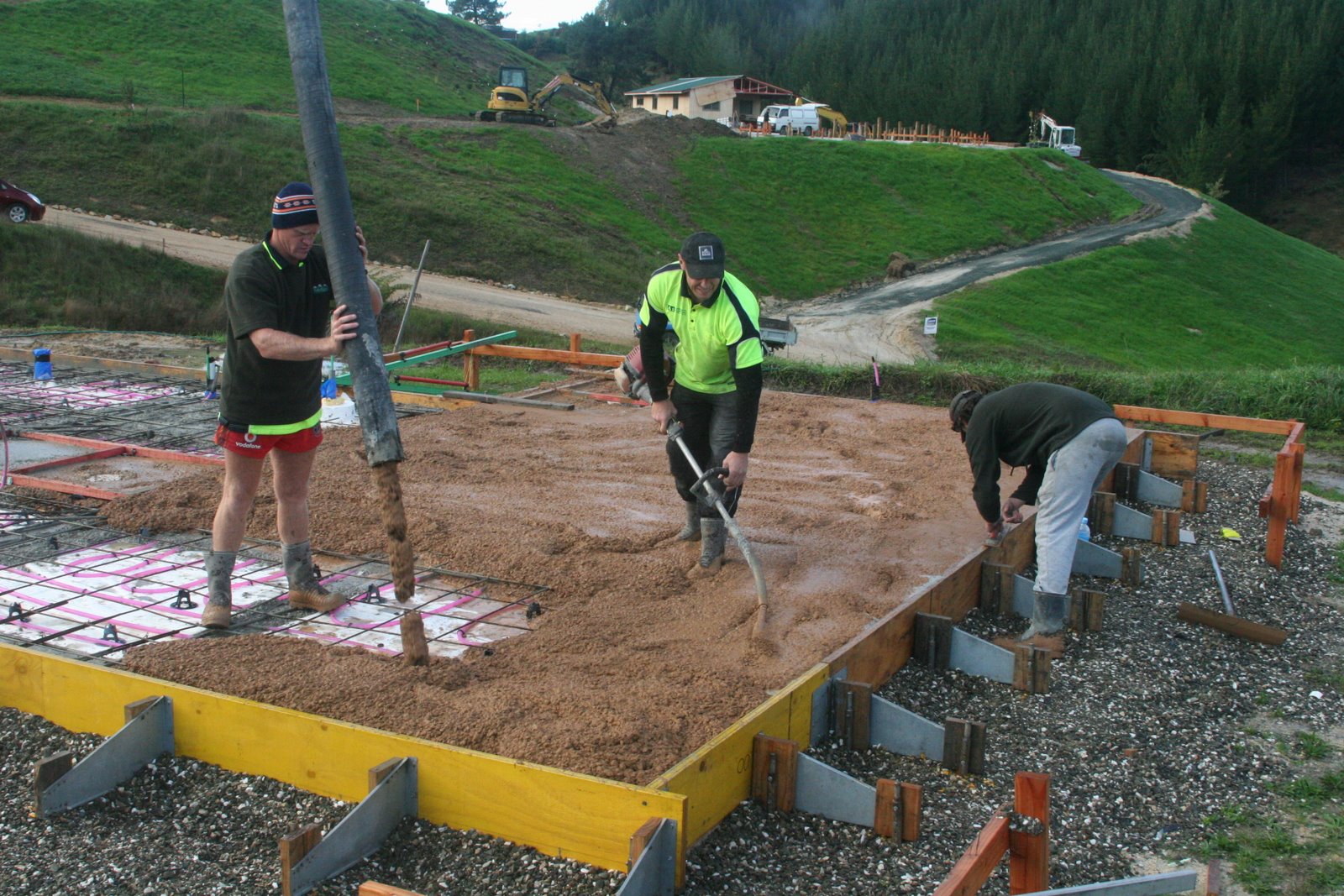
The first thing will be to pump the normal 20MPa concrete into the ribs and vibrate it so it molds nicely in the rib and secures well to the rebar. For this purpose a hand held "weed whacker" type looking device with a vibrating thingy on the end is placed in the concrete. This was certainly a very effective tool for the job.


 |
| And as the sun rises, look what we get :) Must be a good day for it then ... surely! |

 |
| The pumper truck is quite interesting too. It has a trough at the rear where the concrete mixer backs up to to empty its load. Here you see the coloured concrete which will be pumped next to make up the 100mm slab over the ribs. |
 |
| This thing that looks like a mini nuclear reactor is the pump assembly. The pump works by having a large flexible pipe which is pressed in by rotating rollers, just like how you'd squeeze the last bits out of a tooth paste packet. This isolates the pump mechanism from the pipe containing the concrete, which makes for easier clean up. I think this is known as a peristaltic pump. |
 |
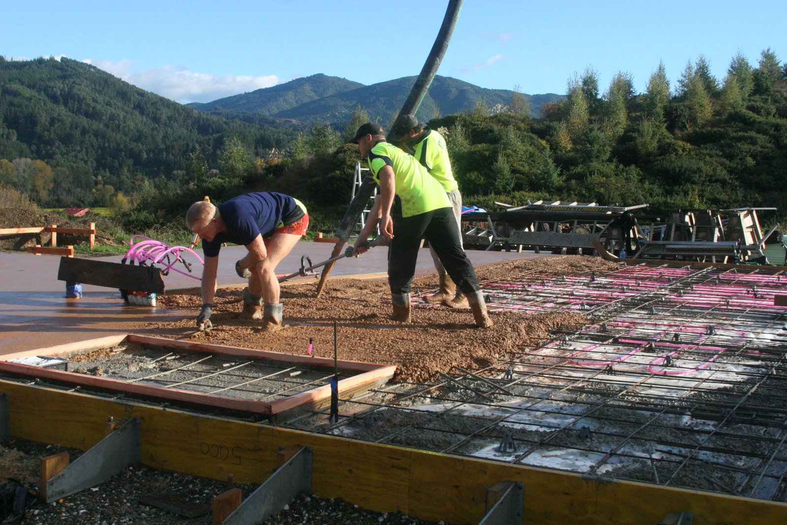
| Once the concrete is pumped and vibrated down, it is trowelled first to get a flat surface finish. |

 |
| Subsequently this flat-tool-on-a-stick contraption (otherwise known as a Bull float) is used to get a smoother surface. This is repeated until the entire floor is done and looking smooth. |
 |
| The hydronic pipes were pre-filled with water and pressure tested to ensure that there were no leaks. Here you can see the pressure gauge is still reading non-zero, which means the pipes are still in good integrity. The pressure sensor will remain in place right through the rest of the build, especially important for when the cutting of the concrete will commence for control joins, as well as when the wooden framing gets attached to the floor. |
 |
| And when they are done, they ensure everything is washed clean so that there is no concrete residue on anything. |
 |
| To finish this stage, a Kelly float is used to polish up the floor so it becomes nice and smooth. This is how the floor will remain for the duration of the build, until we fine polish it one step further and then seal it. |
 |
| The next day the boxing is stripped away showing the slab in all its concrete glory. You can even see the layering of the coloured concrete over the edge ribs. It is quite impressive to think that this is basically a very sophisticated piece of rock work :) |
Now that the concrete has had a couple of days to set, the concrete cutter comes to cut a control expansion joint in the slab to help reduce chance of cracking. Our engineer has advised that the expansion cut should be done at a place where there is the highest likely hood of cracking which is 10-20mm off the rib's edge. The rib itself is pretty strong with all the reinforcing and thus the highest areas of tension is in the place immediately adjacent to the rib. Hopefully this will be good enough to help keep the slab from future cracks.


However we expect that despite all this measures, we might still get cracks - something that is entirely part of what concrete does.The expansion joint will be filled with grout later, or a piece of metal before the polishing commences.
Phew, now we are done - what a journey!! I'm sure the rest of the build will pose its own challenges, but I'm really glad that our foundation has been poured and I can breathe a sigh of relieve ...
... until next blog!
Adios amigos!
:)


Wow, awesome, lots of planning and knowledge involved indeed. How many more will you plan/sell?
ReplyDeleteBut really, remember there's a pot of gold at the end of a rainbow? Look at the photo, you buried it in concrete!!
Hmm, I think I'll stop at one house :) ... although we might consider a granny flat some time in the future.
DeleteAs for the pot of gold? ... oh how I wish that were true. Might be worth destroying the slab to get it ;)
I presume you checked that all those different electrical cables can be put down the same conduit? There are often funny historical rules about that sort of thing.
ReplyDeleteConcrete cracks can also be filled with epoxy. I've seen this at work and my parents are about to do it too.
Ed
Hmm, you may have a point there. The cables I am getting are double insulated for the phase and neutral sleeved, I would have thought this would be ok. If it isn't, I can always put a conduit within the conduit, say for the comms lines, and leave the rest of them exposed in the main conduit. There should be enough space for that. In fact I'm running the CAT6 in a LDPE pipe anyway as it works out a bit cheaper than running CAT6 gel cable in there.
DeleteIt aught to be OK but the law isn't always logical, as I discovered when looking into Dennis's idea of putting AC and DC down different phases of a single 3 phase cable (not allowed). Conduit inside conduit sounds way too ingenious to be allowed either. I'd be interested to hear what you find out - that's a cool one to know if it is.
DeleteIs your DC still only 48V? It will help that it is below the 125V ELV threshold and not the usual ~400V level of a large PV array.
Actually I did ask the electrician if I could use a single 4 core NS cable for 2 AC phases and one DC pair, and he said you can't mix voltages on a single cable like that legally. This is understandable because somebody might later think it was standard 3 phase and do something stupid - not that you can entirely stop stupidity, but certainly limiting its scope is probably a good thing. However I think it isn't difficult to run an extra seperate single core cable for the DC link at the same time - just a wee bit more expensive.
DeleteYes I'm still on 40-60V from the NiFe, and this bus will be used to drive the Lorentz water pump as well as run a DC circuit in the future for lightning without AC conversion losses. It also means I am less limited by the output of the AC inverter.
Not quite the 230V DC bus I was hoping you'd do for all appliances but a good compromise! Have you thought about in some rooms using LEDs with motion sensors built into the bulb? They are getting quite common now for 230V AC (I haven't checked out 48V DC) and could be a good way to save power from lights that would normally get left on unnecessarily.
ReplyDeleteRegarding the electricians comment; by insisting the DC go in a separate cable, he hasn't really limited the scope for stupidity, just moved it to another place. Sure, a stupid electrician will not go awry when dealing with the common AC cable, but then anything could happen when he goes to work on the DC cable if he is basing his actions entirely on the cable's outer appearance (which it sounds like he is) and isn't paying attention to the labels on it or testing it with his voltmeter. So combining the 2 cables into one, and labelling it, is exactly the same scope for risk (assuming the electrician can read). I think this rule simply stems from the historical convention that houses never had any high power DC wiring and will be forced to change in future once DC wiring becomes more common due to PV systems.
Yes, I came across those LED buls too with sensors in them, but they are generally quite piddly in terms of lumen output. I've purchased some sample panel lights with 1600lm output for 18w, which isn't bad - I'll have to see if they are worth while pursuing or not.
DeleteAnd yes yes quite right Anonymous Ed, stupidity does know no boundaries. I'll have purchase another DC breaker for the house (one for the inverter so far), its a good thing my voltage isn't any higher, or I'll have to go out into another world of breakers, and another price bracket.
I wonder what 48V appliances I can buy now :) Oh Neville would be so proud!
Haha, try buying a 600V DC breaker for an electric car! I don't even know where to look.
ReplyDeleteI've been playing with LEDs too. What I've found is the shape is just as important as the lumens (or the power if they don't specify lumens). I have a 12W one that lights the room less than a 6W one simply because it is a spotlight and the 6W is a globe.
Yes I went down that path of HVDC breaker a while ago when I was doing my EV conversion, that never was. You might need to employ a kilovac/gigavac contactor:
Deletehttp://www.evsource.com/tls_gigavac.php
But you need to ensure that your certifier is ok to allow an electrical disconnect instead of a mechanical one, esp for such a high voltage. You can tell him that it is much safer than having a mechanical contactor. This is also by far the cheapest way to do it.
I also bought a 50W LED flood light with a sensor switch on it, that comes in at 100lm/w - so I'm sure the directionality and how much you have infront of the LED as a lense is what causes the drop in lm/watt. If any of them zombies appear, I'll use it as my "death" "ray" ...
This comment has been removed by a blog administrator.
ReplyDelete